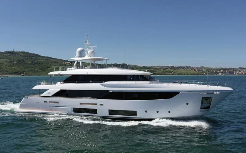
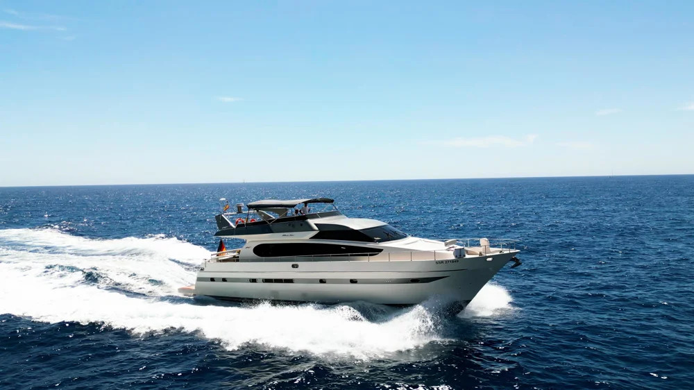
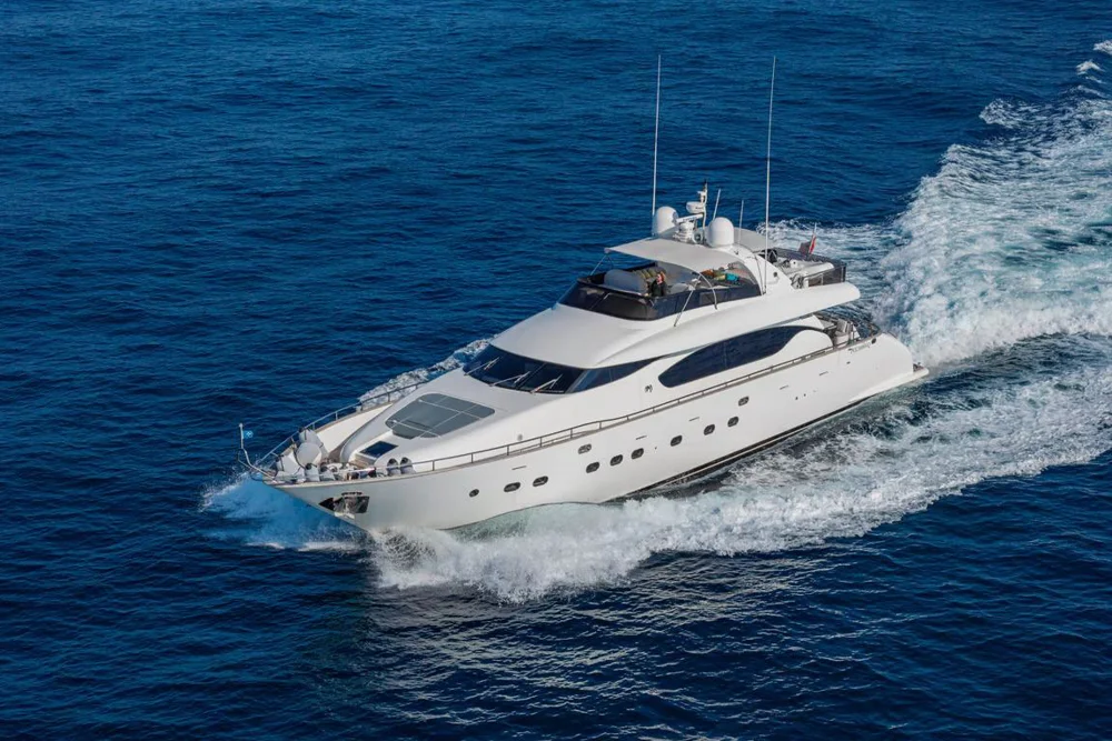
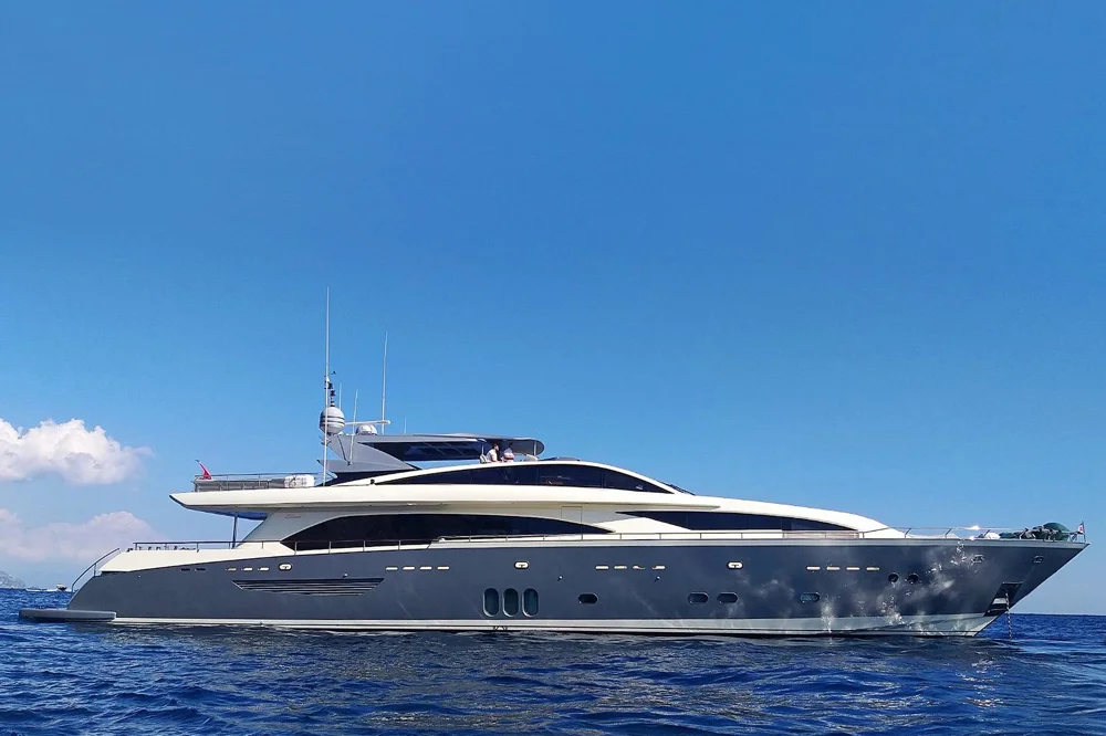
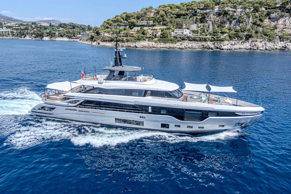
Featuring a rounded bow for improved stability and seaworthiness, the Custom Line Navetta 33's maximum range of 2,000nm will afford extended Mediterranean cruising. Her MAN 1400 engines of 1,400mhp/1029kW (each) at 2,300 RPM will deliver an excellent top speed of 15 knots. In order to reduce noise and vibration levels, a flexible joint has been placed in the transmission lines to absorb any shaft vibrations plus hydraulic fin stabilizers with zero speed mode are fitted as standard for comfort underway. ADELIA features a range of technical innovations such as the patented DMT system for optimum use of the stern area, VOTIS software for flexible management of the onboard infotainment systems and an integrated helm station for monitoring all systems and equipment.
ADELIA provides accommodation for up to 10 guests in 5 spacious staterooms, with the full-beam owner's stateroom situated on the main deck. There is a fold-out terrace offering superb sea views from the main salon, while the upper deck features sliding windows so the area can be easily opened up. A popular hotspot is the sundeck, complete with spa pool and large area for sunbathing.
For a yacht of this size, the Custom Line Navetta 33 offers the Owner and his guests a lot of internal volume. The main salon, with its fine Italian-style interiors and fold-out terrace, is every guest's favourite spot on this yacht, together with the spacious sundeck which is furnished with beautiful Minotti free-standings to emphasize the Italian “dolce vita” style even further".
Please contact Jelena Vezia at +33 642 941 461
Please contact Jelena Vezia at +33 642 941 461
Ship systems will be designed, supplied and installed by the Builder as per the Builder standard in accordance with Classification Rules.Bulkhead penetrations will be carried out in accordance with provision of the RegulatoryBodies.Piping connections will be basically defined on each paragraph dedicated to the singlesystem; different connection methods will be used but anyhow in compliance withthe Classification Rules.Drip trays in plastic material or stainless steel will be provided as optional for pumps andother machinery; they will be equipped with sleeve and plug.Valves selection will be proper for the physical properties of the piping system such aspressure, temperature and fluid viscosity. Valves will be manually operated if not otherwisestated. Quick closing valves will be locally and remotely controlled from theemergency control position.
Two four stroke diesel engines suitable for marine propulsion will be installed on the foundationsin the engine room, one each side:Manufacturer MANModel V12 LE446Rated power 1400 mhp / 1029 kW (each) @ 2300 RPMOperation profile will be up to 1000 hours per year at a maximum of 20% of time at fullload, average load <50%. Exhaust emissions are in compliance with EPA TIER III regulations.Colour will be white with RAL according to Maker's standard.
COMPRESSED AIR SYSTEMOne electric driven compressor unit having a power requirement of about 2kW will beinstalled in the engine room; air will be delivered at a maximum pressure of 7 bar, togetherwith a reservoir of approximately 8 litres. Drip tray will be installed as optional.The system will supply compressed air to the horn and through a pressure reducing valveto the connection in engine room.
SCUPPERS AND DRAINAGE SYSTEMScuppers and drainage system will be provided to collect and discharge outboard thewash down and rain waters from external decks. They will be equipped with removablegrids in stainless steel. Above freeboard deck, pipes will be made of PVC and flexiblehoses. Below freeboard deck scupper lines will be in ISO 13363 flexible rubber hoses.The aft garage will be drained through one automatic 24Vdc pump connected overboard.A second 24Vdc self priming pump sucting from a stainless steel collecting tank(fitted with vent and level switch safe for petrol) will allow to discharge overboard or tothe Marpol flange by acting on a three way manual valve.
SEA WATER COOLING PIPINGSea water will be used for cooling both the main engines, the gearboxes and the exhaustgases; there will be two independent systems, one for each side. One manualthree way valve mounted on each propulsion cooling system will allow to supply seawater to the opposite gearbox with one main engine running.Shaft seals will be provided by an independent cooling piping system, one on eachside; a second cooling line will be provided by a branch connected to the gearboxoutlet.Piping will be ISO 15540-15541 corrugated rubber hoses for main engines, gearboxes,shaft seals, and bow thruster cooling system, while ISO 13363 corrugated rubber hoseswill be used for main engine gas cooling system. Connections to the engines will beflexible and in accordance with the manufacturer installation instructions.Generators sea water piping will be ISO 13363 corrugated rubber hoses; each unit willbe feed by its own circuit.Sea chests will be in bronze and installed with the related sea chest strainers; in theengine room there will be:• n.2 sea chests for main engines• n.2 sea chests for diesel generators• n.1 sea chest for fire pump• n.1 sea chest for air conditioning system• n.1 sea chest for bow thruster hydraulic oil cooling system• n.2 sea chests for the shaft sealsTwo electric pumps, arranged in parallel, will supply sea water to the heat exchangerfor cooling the bow thruster hydraulic oil.
MAIN ENGINES GAS EXHAUST SYSTEMThe exhaust gas of each engine will be led mainly underwater and above waterlinelevel through a GRP pipe installed into each sponson. Metallic compensators will beprovided at the engines gas outlets; from there the gas will be ducted to the silencerunit installed over the main engine and then it will be cooled down by sea water andthen brought overboard.The silencer will be installed on a white painted steel frame while a polished stainlesssteel pillar will be provided to support the gas exhaust ducts. The equipment will beresiliently mounted in order to minimise noise and vibration. Elastic resilients will be ofthe low frequency type and protected against the high temperatures in order to avoidany rubber modification which would lessen the resilient damping properties.The duct will be made of stainless steel AISI 304 for the dry part and in AISI 316L stainlesssteel for the wet part. Sea water pipes will be made by ISO 13363 flexible hoses.
Tropicalized air conditioning system fresh air intake ventilationJacuzzi up to 4 pax with lighting, fast filling/emptying system, must be empty underwayBalcony 1mx2m on main deck opening out from saloon with seatingWine cellar on upper deck and one on the main deck in the pantry. 3 Icemakers total. Electric plancha on sundeckShaded sitting area with table on foredeck and sun pad areaBeach club on garage platformSun pads around Jacuzzi on sun deck and two circular sun loungers
ANCHOR AND MOORING EQUIPMENTTwo High Holding Power type anchors in galvanised steel will be fitted in stainless steelanchor pockets. Each unit will weigh about 140kg and will be connected to the hullthrough a chain 14mm in diameter made in galvanized steel, with stud link and havinga length of 125m each (5 lengths). Chain is painted in white/red for length visualcheck. Kenter joining shackles are provided. The system will be sized according to theClassification rules.
MOORING BOLLARDSPolished stainless steel AISI 316L bollards will be fitted as follows:• n. 4 on the forward manoeuvring area mounted onto the deck (2 for each side)• n. 4 on the aft raised mooring areas in the main deck cockpit (2 for each side)• n. 4 horn type integrated in the fairleads, fitted on the main deck side bulwark (2for each side)• n. 2 on the aft platform (1 for each side)• n. 4 horn type integrated in the fairleads, fitted on the main deck side bulwark (2for each side)• n. 2 on the aft platform (1 for each side)
FAIRLEADSPolished stainless steel AISI 316L fairleads will be fitted in the main deck bulwark as follows:• n. 2 on the forward manoeuvring area (1 for each side), with roller• n. 2 with integrated bollard, fitted on the side bulwark (1 for each side)• n. 4 on the aft raised mooring areas in the main deck cockpit (2 for each side)
WINDLASSESTwo electrical windlasses vertical type (4kW, 400Vac/50Hz/3ph) dual rotation at singlespeed, will be fitted on the foredeck, bolted to the deck and locally controlled bymeans of a hand wired controller. Each windlass will be equipped by a stainless steelgypsy, one stainless steel drum and mounted close to a chain roller mounted on top ofeach hawse pipe and equipped with a devil's claw. A polished stainless steel plate willbe fitted below the windlasses to protect the gelcoat and facilitate the removal of dirt.The system will fulfill the requirements of the Classification rules.
CAPSTANSTwo foot switch electric operated vertical capstans (about 2,2kW, 400Vac/50Hz/3ph)will be fitted on the raised mooring area built on each side of the main deck cockpit.Each unit will be dual rotation at single speed type.
Crew call on all decks (master, main deck saloon, upper deck saloon, aft deck cocktail, upper deck cockpit, sundeck, foredeck)Audio system Apple air play connected in 5 zones (upper deck saloon, main deck saloon, main deck aft cockpit, aft upper deck cockpit, sun deck)Guest cabins: TV, DVD, satellite TV Canal +/Canal Sat and Bluetooth sound systemMaster cabin: TV Dolby 55', DVD, Canal +/Canal Sat TV Bluetooth sound systemSun deck: 180 degrees rotation TV 49', DVD, Canal +/Canal Sat, Air play musicMain deck saloon: TV, DVD, Canal +/Canal Sat, Air play music, Playstation 4 with gamesUpper deck saloon: TV 55', DVD, Canal +/Canal Sat, Air play music, Playstation 4 with gamesBeach Club: music system 9.7.1 TV AND HI-FIA TV-Sat antenna will be fitted on the hard top, with an empty dome for symmetry.Release 04 - 10.2020 Page 59 of 75Custom Line Navetta 33
MAIN SALON• n°1 TV 55’’LED with electric ceiling system• Home Theatre system with amplifier tuner (5+1) connected to central server unit• Apple-TV• I-pad mini control system for entertainment• TV SAT receiver common interface• HDMI Aux input
OWNER’S CABIN• n°1 TV 49’’LED smart tv• Home Theatre system with amplifier tuner (2+1), connection to central server unitand Apple-TV• I-pad mini control system for entertainment• TV SAT receiver common interface• HDMI Aux input
GALLEY:• n°1 Mini Hi-Fi USB/BT system with tuner• n°2 loudspeakers
MAIN DECK EXTERNAL AFT:• n°4 waterproof loudspeaker connected to main deck salon, airplay, party modeand volume control
VIP AND GUEST CABINS:• n°1 TV LED 43''for VIP cabins and portside guest cabin, 32''for starboardside cabin• n°2 loudspeakers• Media server system with Apple TV connected to central unit• HDMI Aux input
CREW MESS:• n°1 TV 24’’LED• n°2 loudspeakers• Mini Hi-Fi USB/BTsystem with tunerHDMI Aux input
CREW CABINS:• n°1 Mini Hi-Fi USB/BT sytem with tuner• n°2 loudspeakers
UPPER DECK SALON• n°1 TV 49’’LED with electric ceiling system• Home Theatre system with amplifier tuner (5+1), connected to central server unit• Apple-TV• TV SAT receiver common interface• HDMI Aux input
WHEELHOUSE:• n°2 loudspeakers connected to the Captain's Cabin mini Hi-Fi
CAPTAIN CABIN (upper deck):• n°2 loudspeakers• Mini Hi-Fi DVD/USB/I-POD with tunerHDMI Aux input
WHEELHOUSE:• n°2 loudspeakers connected to the Captain's Cabin mini Hi-Fi
IT SYSTEM:• n°4 access point Wi-Fi• Network switches system• 4 G/LTE Modem• Wi-FI bridge• TV SAT
Two diesel generators with the following characteristics will be installed in engine room:Manufacturer KOHLER®Rated power outputs: 44kW
GENERALA modern and complete marine electrical system will be supplied and installed. Specialattention to be paid to the design and components used in order to prevent problemswith harmonic distortions, low insulation and EMC. As far as practicable and possible, allelectrical equipment will be installed so that it will be easily accessible for maintenance.The electrical systems will consist of:• power supply system• distribution system• lighting system• alarm systemThe following voltages will be used:• 400Vac/50Hz/3ph for power.• 230Vac/50Hz single phase for lighting purposes, small users and households.• 24Vdc for services and emergency lights, safety circuits and for the navigationinstruments.• 12Vdc for diesel generators (DDGG) starting systemPower will be supplied by:• diesel generators• emergency power• shore connection• batteries• UPS for all data communications and essential bridge servicesThe electrical equipment, wiring, fixtures, boards, switches etc. will be designed, installedand tested according to the Classification Rules requirements. All cables shallcomply with Classification Society requirements and IEC 60092-507. Cables within thehull will be installed on galvanised steel, painted Aluminum alloy or flame retardant PVCtrays and secured with metal and plastic clips according to the Builder installation instructions.Secondary routes will be made in PVC flame retardant. Cables wires colorswill be determined by the Builder and set for neutral, positive and negative wires. Penetrationsof watertight bulkheads will be made through watertight multi-cable glandsor equivalent approved sealing systems.
CABLINGRouting of cabling will be designed so that interference between systems is minimizedto a level in accordance to the EC Directive. In all accommodation and technicalspaces 230V sockets will be installed.
POWER SOURCES PARALLELLING SYSTEMA synchronising and load sharing system between the generators will be provided asOPTIONAL. A local-remote switch will allow to manually connect the generators in parallelto manage it automatically. The system will manage the power requests fromthe yacht electrical users and will be controlled through the central monitoring system.Gradual exclusion of non-preferential appliances will also be provided in the event ofan overload. This system generally known as SLS (Selective Load Shedding) will allow todecrease the power request as the system approaches maximum capacity or a certainlimit (% of rated power) set by the operator and before overloading the generatorsor shore system. This condition will be shown on the monitoring system and allow theengineering staff to bring a second generator on line. The systems departing from theboards will be protected by switches.
SHORE CONNECTIONAs a standard supply one 3 phase isolation transformer 70kVA, 400Vac input, 400/230Vacwith neutral output will be installed. One 100A socket with about 30m cable will be provided.One (1) Electric devices for handling the portable power cable will be providedat stern, type Glendinning or equivalent. A frequency converter system made by twounits (master and slave) can be installed as optional, with the following characteristics:Power: 2x36kVAInput voltage: 3 phase 170-520VOutput voltage: 3 phase 400VInput frequency: 40-75HzOutput frequency: 50HzCooling: Air cooledConnections: n°2 cable
BATTERIESThe following groups of batteries will be installed:• Two groups 24Vdc (one per unit) for the start of the main engines; fed by a batterycharger• Two groups 12Vdc (one per unit) for the start of the diesel generators; fed by abattery charger• One group for the 24Vdc emergency supply; fed by a battery charger• One group 24Vdc for the radio station; fed by a battery charger• One group for the 24Vdc users (services); fed by a battery chargerSealed gel batteries will be used mainly. The capacity of the batteries will be sufficientto comply with the requirements of the Regulatory Bodies and to the Technical Specificationof the engine/ motor manufacturers.The start batteries will be recharged by the alternators installed on the related engineand a dedicated battery charger.The start batteries for the main engines and the diesel generators can be swapped incase of emergency.The status of all batterie
The galley will be ICON model by Ernestomeda, a product customized for the net spaceof the yacht, with integrated appliances installed, matt lacquered finishing and quartzresintop. Colour and materials as per the Builder décor book.
Domestic equipment will be supplied in accordance with the standard appliances Plan.Main salon:• n°1 drawer fridge
Galley:• n°1 electric glass/ceramic 5 burner cooking top• n°1 hood• n°1 oven• n°1 dishwasher• n°1 fridge - freezer• n°1 fridge side by side• n°1 trash compactorPantry main deck:• n°1 microwave oven
A reduction gear box ZF 3050 will be provided for each engine. Reduction ratio determinedon relation to the propeller design and propulsion. Two skewed propellers, 6 blades, diameter about 1.3m, designed to obtain high efficiencyand low noise will be provided.They will be made by nickel- aluminium-bronze (NiBrAl).Each propeller will be statically and dynamically balanced.Manufacturing tolerances will be according to ISO 484/2
CLASS S.Two spade rudders with drive by wire steering control will be provided. The blade sizewill be determined to ensure good manoeuvring capabilities; the rudder will be properlytransversally off-set from shaft line axis in order to remove the screw shaft withoutdismounting the blade. The rudders construction material will be AISI 316L. Rudder holeswill be in stainless steel, rudder stock will be made of Marinox 17 or equivalent, weldedto the rudder blade and sized according to the Classification Rules.
STEERINGThe steering system will be of electrohydraulic type. A drive by wire steering wheel willbe fitted in the wheelhouse, while one joystick will be installed on each side wing. Onthe dashboard a control panel will show the main info (mode, alarm status, rudderangle) of the steering system. The hydraulic system will be made of one power pack(oil reservoir with a 400Vac/50Hz/3ph pump) and 2 hydraulic cylinders (one for eachrudder).
BOW THRUSTERA bow thruster unit hydraulically driven (85hp) will be installed in a dedicated space.The propeller will have fixed blades and will be fitted in a 20in tunnel. The installation willbe executed strictly according to Manufacturer instructions and specifications. Gridson bow thruster tunnel will not be provided in order to maximize the thrust performance.Control Joystick will be installed on the main helm station in wheelhouse and on the wingcontrol stations.
INTERCEPTORSTwo units, one for each side, will be installed on the transom edge actuated by servounits connected with control units. The system will be governed by a control panelplaced in the wheelhouse.
BILGE AND FIRE SYSTEMEach watertight compartment will have a separate bilge suction, with foot valve, connectedthrough the main bilge manifold to the bilge pump.Water from the bilge will be discharged overboard through an overboard connectionlocated in the engine room. Main engines cooling pumps can be used to draw waterfrom the engine room bilge in case of emergency.A second bilge suction will be installed on each watertight compartment, with footvalve, connected through the emergency bilge manifold, to the emergency bilge/firepump and discharging overboard through a three way valve. The emergency bilgemanifold will be installed out of the engine room. Where drainage is not necessary, thearrangements may be omitted provided that yacht safety will not be impaired.The chain locker will be self draining, additionally one bilge suction connected to a dedicatedhand pump will be provided. A bilge alarm system, connected to the alarm andmonitoring system, will be installed in all compartments served by the bilge system. Thebilge pumps can be started and stopped from the control panel.Bilge lines will be flexible hoses fire resistance (ISO 7840) inside machinery spaces whilefire resistant (ISO-13363) hoses outside machinery spaces; the manifolds will be madein AISI 316 stainless steel.
The fire fighting system will have its own pump placed in engine room, and will be connectedto the bilge system through the main manifold in such a way that the bilge andfire-figthing pumps may serve as bilge pumps and vice-versa. The emergency bilge/firemanifold placed out of the engine room will allow to use the diesel motor pump forfeeding the fire fighting system too, by suctioning from a dedicated sea chest.Fire hydrant valves, with fire hoses and nozzles will be fitted.
BILGE PUMPOne electric self-priming centrifugal pump 400Vac/50Hz 3ph 4kW will be installed in theengine room for main bilge system. The pump can be by-passed with the electric firepump.
FIRE PUMPOne electric self-priming centrifugal pump 400Vac/50Hz 3ph 4kW will be installed in theengine room for feeding the fire extinguishing system. The pump can be by-passed withthe electric bilge pump.
EMERGENCY DIESEL MOTOR PUMPOne diesel motor pump will be installed, in the port side of beach area technical space,for servicing the bilge and fire system.
ENGINE ROOM EXTINGUISHING SYSTEMA fixed gas fire fighting system (FM200 or equivalent, to the Builder choice) will be installedin the engine room. A sound and visual alarm will be provided in the engineroom operating automatically when fire alarm is activated.
AFT GARAGE EXTINGUISHING SYSTEMThe aft garage will be equipped with a fire fighting sprinkler system fed by sea water(see fire fighting system).
The Yacht will be delivered with life saving and fire appliances, as per Italian BodiesRequirements.The yacht will be equipped with the following life saving appliances:• Housed life buoys (2), one with rope and 30 mt light buoy2 Life rafts for 10 people each (total 20 people)• 20 Life jackets• 2 Child life jackets• 1 First aid medical kit• 1 SART Transponder• 1 EPIRBThe yacht will be equipped with the following firefighting appliances:• foam extinguishers• powder extinguishers• CO2 extinguishers• fire blanket
NAVIGATION SYSTEMAn innovative integrated dashboard with navigation and automation system will beprovided in the wheelhouse. The dashboard will be composed by:• 3 x 15” displays, vertical• Jog system control• Bow thruster control lever• Main engines throttles• Main engines start/stop buttons and alarm signals + emergency stop buttons• Main engines key• Autopilot• 2 VHF (class D DSC)• Alarm buzzersThe integrated dashboard will allow the visualization and control (where indicated) of thefollowing items:• Navigation Monitors configuration Management• Wheel House Device control scene Management (OPT)• Language selector (Italian – English)• Integrated monitor brightness control (Hatteland)• Wiper control• Horn control• CCTV control• Search light control (OPT)• Fog Horn signaling control• Wheelhouse light control• Navigation Light control• Heading• Roll & Pitch• Wind direction and speed• SeaThe integrated dashboard will allow the visualization and control (where indicated) of thefollowing items:• Navigation Monitors configuration Management• Wheel House Device control scene Management (OPT)• Language selector (Italian – English)• Integrated monitor brightness control (Hatteland)• Wiper control• Horn control• CCTV control• Search light control (OPT)• Fog Horn signaling control• Wheelhouse light control• Navigation Light control• Heading• Roll & Pitch• Wind direction and speed• Sea depthReleaseYacht speed• Compass light control and dimmer• Steering control panel• Stabilizer System• Tank levels, including high and low level alarms• AC power page (main parameters of converter, shore power and generatorswhere installed)• DC power page (main parameters of the main items fed by DC current)• Batteries• Main engines• Gearboxes• External doors and hatches and portholes (where applicable)• Shell doors• Internal watertightShell doors• Internal watertight doors• Bilge Alarms• Fire detection system• Water maker (According signals made available from the water maker as permanufacturer’s standard)• Bilge & fire pumps control• ER ventilation control• Vessel name (where back-lit)• Underwater lights control• External lights and cabin lights controlWheelhouse panel lay-out and location of navigation and communication equipmentwill be illustrated to the Buyer’s Representative. The most updated version of the equipmentat the time of installation, which may be different to the above mentioned, will beinstalled at builder choice. Extra or different instruments may be supplied as an option.Extra costs may apply.Wing stations:Two control stations will be positioned externally at both sides of the wheelhouse andwill include all the necessary commands and instruments for manoeuvring the Yacht inmooring operations:Release 04 - 10.2020 Page 54 of 75Custom Line Navetta 33• Steering tiller• Slave bow thruster control lever• Horn• Main engine throttles• Main engines start/stop buttons and alarm signal, emergency stop buttons• Rudder angle indicator• Engines RPM gauges• Alarm buzzers
NAVIGATION EQUIPMENTThe following navigation equipment will be supplied and installed:• 1 autopilot system, micro-processor controlled, with feedback system• 1 echo-sounder• 1 wind station• 1 multifunctional transducer (Depth, Speed, Temperature)• Navigation sensors including:– n.1 radar, 6kW Furuno, open array, X-Class antenna– n.3 GPS– n.1 Flux gate system– n.1 magnetic compass– n.1 Weather station• Charting plotter system including:– n.2 independent processor black box
NAVIGATIONSteering tiller• Slave bow thruster control lever• Horn• Main engine throttles• Main engines start/stop buttons and alarm signal, emergency stop buttons• Rudder angle indicator• Engines RPM gauges• Alarm buzzers
NAVIGATION LIGHTSThe navigation lights will be according to COLREG 72 regulations. As reference, thefollowing approved lights will be installed:• n.1 white, masthead, navigation light• n.1 white, stern lights• n.1 red, port navigation light• n.1 green, stbd navigation light• n.1 white, anchor light• n.4 red, not under command lights.The navigation lights will be controlled by a panel installed on the wheelhouse. Audibleand visual alarm to be provided to indicate failure of any navigation light.9.1.3 HORNOne (1) air horn will be installed.Air pressure type with solenoid valve connected to the main air pressure system with localair receiver complete with control panel with fog signal timer installed on the bridge.
MONITORING SYSTEMThe Alarm and Monitoring System (AMS) will display a few yacht data by means ofmonitors positioned as follows:• n.1 integrated in the dashboard in wheelhouse (15”)• n.1 touch screen in the crew mess (15”): only the AMS pages will be shown• n.1 in the engine control room (15”): only the AMS pages will be shownThe system’s general architecture is based on one or more electronic I/O modules thatare connected to the onboard devices, a network cable that connects them, one ormore main processors (CPU), and one or more LCD displays or PCs with touch screen.
COMMUNICATION SYSTEMThe radio installation to be of the approved (wheel marked) type where and accordingto the requirements of the Regulatory Bodies as applicable and to the GMDSS specifications,areas A1, A2 and A3. The following equipment will be installed as standard:• 1 VHF radiotelephones with DSC GMDSS class A• 1 VHF radiotelephones with DSC GMDSS class D with 3 handsets in Wheelhouse,Captain’s Cabin, Crew Dinette.• 2 portable VHF GMDSS apparatus.• 1 radiotelephone SSB GMDSS – DSC• 1 NAVTEX receiver• 1 EPIRB 406MHz, GMDSS, with hydrostatic release.• 1 radar transponder, GMDSS (SART)
NETWORK/TELEPHONE SYSTEMThe IT system will consist of a LAN network and a dedicated WIFI network for on boardinformation technology services, on board entertainment and AV systems. The systemwill be compatible with latest protocols and technology available at the time of installationof the equipment. PC’s, laptops, tablets and other devices used for on-boardinformation technology will be Buyer’s supply.The yacht will be provided with an internal communication system controlled by a PABXcentral unit. Cordless telephones and RJ45 Ethernet plugs will be placed in the followingareas:• wheelhouse• main deck salon• galley• upper lounge• master cabin• vip cabin stern starboard side• vip cabin stern port side• guest cabin starboard side
INTERCOM SYSTEMAn intercom system fed by the emergency supply line will be installed in the followinglocations:• n.1 Central station with microphone in the wheelhouse• n.1 Talk back station with headphones in the engine room at the local enginecontrol post• n.1 Talk back station at bow mooring post• n.1 Talk back station at stern mooring post.Release
CCTV SYSTEMCCTV surveillance system will be provided with n.6 cameras positioned as follow:• n.2 colour day/night camera in engine room• n.1 colour day/night camera in engine control room• n.2 waterproof camera on the ceiling in the external main deck corridor (one foreach side)• n.1 waterproof camera on the ceiling in the external main deck cockpitThe cameras will be placed for best view and so that normal lighting does not blind thecameras. The system will be integrated with the monitoring system.A high standard integrated audio video (AV) system with centrally installed media server,satellite receiver and other necessary equipment will be installed according to the AVMatrix below. Luxury and crew areas will be provided with LED TV’s and appropriatesound systems as described in the below AV matrix. The TV system will be based on one(1) KVH, or equivalent, satellite antenna and one (1) omnidirectional land antenna withTV, AM/FM. Standard cabling for an integrated system will be included in all areas. Acentralized entertainment system will be provided, with 2 main rack units placed in adedicated area (as per General Arrangement Plan). The system distribution will be accordingthe following audio video matrix.
The Company offers the details of this vessel in good faith but cannot guarantee or warrant the accuracy of this information nor warrant the condition of the vessel. A buyer should instruct his agents, or his surveyors, to investigate such details as the buyer desires validated. This vessel is offered subject to prior sale, price change, or withdrawal without notice.
Detalles
FabricanteCustom Line
ModeloNavetta 33
Año (construcción / reforma)2021
Eslora33,0m
Capacidad máxima10
Motores1
Manga7,7m
Especificaciones
Dimensiones
Eslora total33,0m
Manga7,7m
Casco
MaterialGRP
DiseñadorZuccon
Botadura2021
Alojamiento
Camarotes de invitados5
Baños6
Aseos de tripulación3
Máximo de pasajeros10
Prestaciones
Autonomía1 nmi
Propulsión
Motor 1
Marca del motorMAN
Modelo del motorV12 LE446
Tipo de combustibleDiésel
Los detalles de esta página son proporcionados por Ocean Independence - Europe como material comercial. Contacta directamente con el bróker para obtener toda la información.